
data-animation-override>
“After selling a more powerful car, a near-stock 302 Windsor was never going to cut it for this Mustang’s owner”
Words and photos: John Mincham [Magnum Automotive]
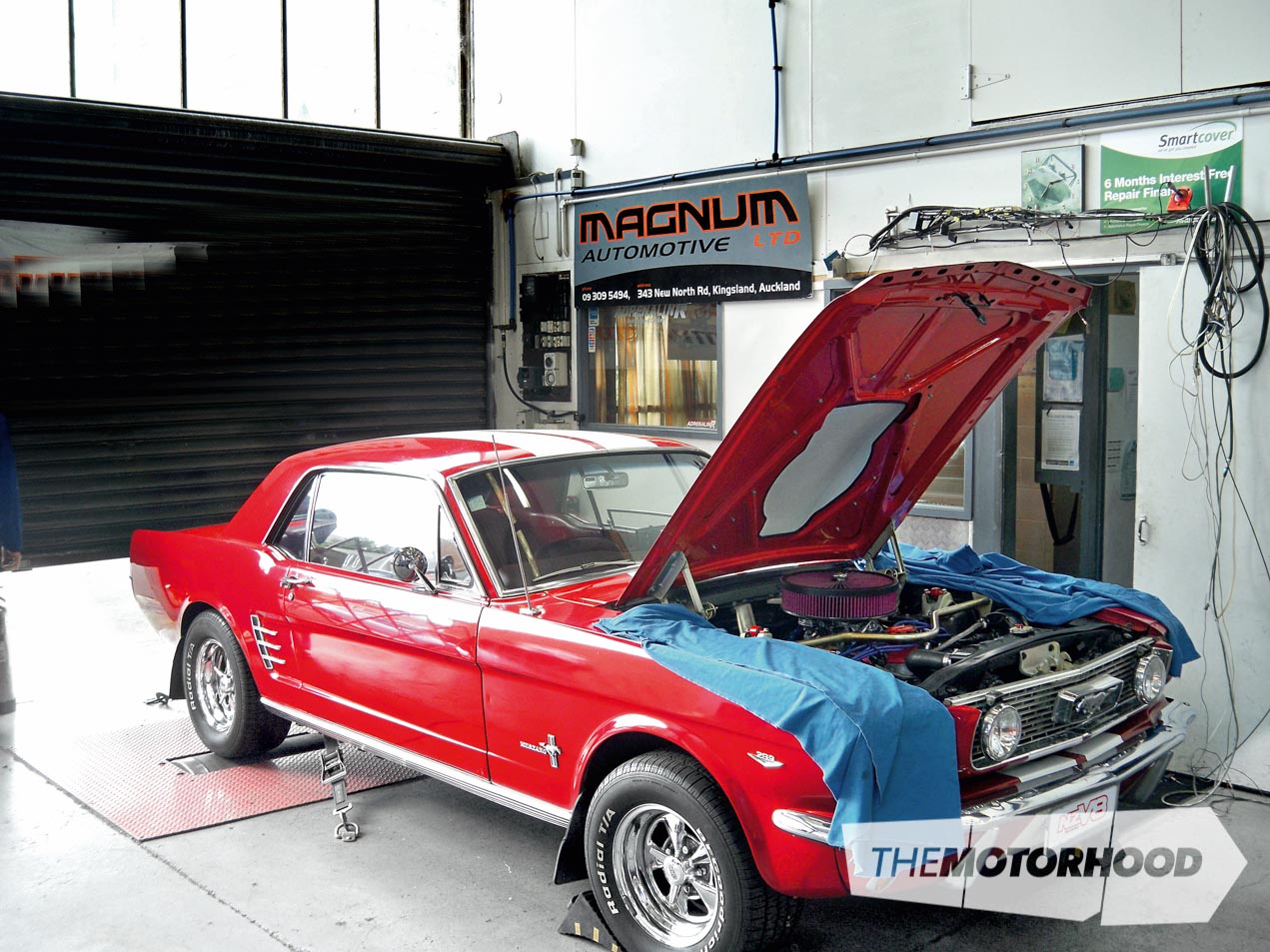
The owner of this 1966 Mustang is a Ford man at heart, but he is also the first to admit that his old 350 Chev-powered Capri had a whole lot more power than his recently purchased Mustang.
When he bought the car, it came complete with a ready-to-run MSD distributor and Quickfuel Slayer carb mounted on an Edelbrock Performer RPM manifold. Even with these parts, the car still had very noticeable flat spots in its power delivery and generally wasn’t running right.
Step one
The first step in the path to automotive happiness for the owner was to get the car running right, and see if that offered enough performance to satisfy him. With the parts already fitted, there was no reason for it to be running as it was — apart from a lack of tuning.
For this, the team at Magnum Automotive were called upon, not only for their expertise, but also because of their in-house rolling road dyno, which makes tuning the car under real-life driving conditions far simpler.
With the car strapped to the dyno, and a few baseline tests carried out, what the owner could feel was confirmed: power delivery was anything but linear.
Prior to the heads being pulled, a leak-down test was conducted to see if it was worthwhile continuing.
The Fix
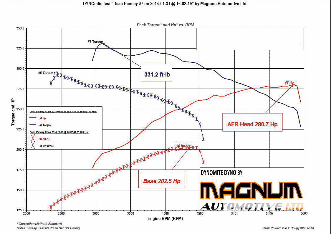
Those noticeable holes in the vehicle’s power were simply caused by a lack of tuning. With some simple adjustments of the carburettor, and adjustment of the timing to an optimal 32 degrees, the car not only ran smoothly but produced an almost respectable 202hp at the wheels at 4400rpm.
The owner took the car for a test drive and was happy with the smoothness of the engine, but unhappy with the overall performance. The car still needed more power!
Step two
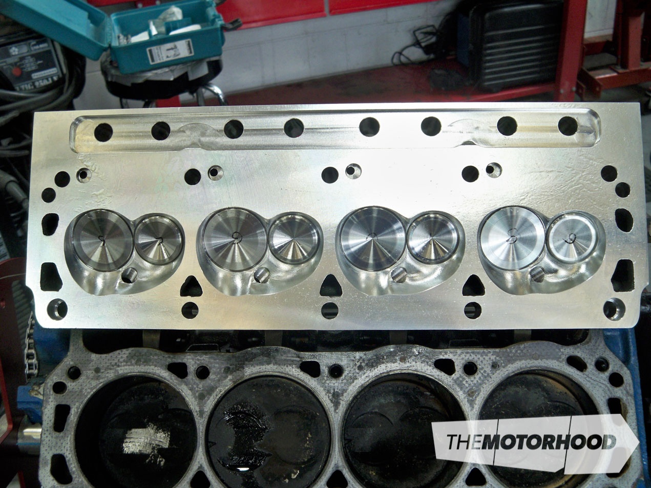
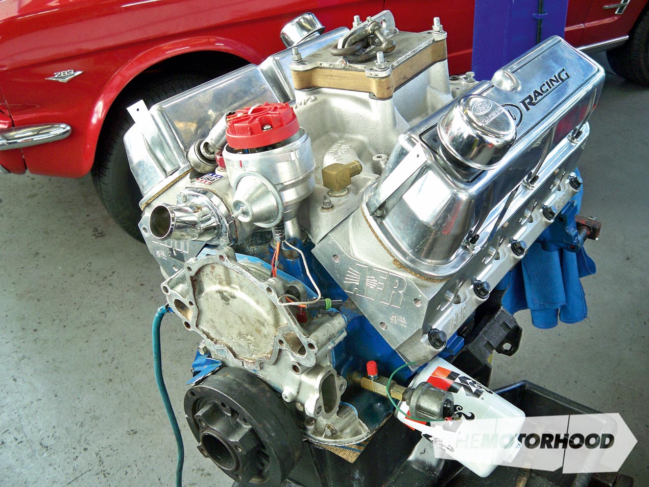
With the MSD ignition, Slayer carb, and Edelbrock intake previously fitted, the decision was made to fit a set of CNC ported AFR185 heads. To make the most of the high-flowing heads, a retrofit-style hydraulic roller cam would also be fitted. While the heads chosen were a touch on the large side, with their 2.02-inch intake valves, 1.60-inch exhaust valves, and 58cc combustion chambers, the owner has made murmurs of a 347ci stroker build somewhere in the future, so the heads were decided to be a good overall compromise between now and later.
The Fix
The car was once again dropped off to Magnum, and the engine was completely removed from the vehicle. This is not always required for a cam change, but due to the fact that the heads were coming off, the block needed to be modified for the retrofit hydraulic roller lifters, and the torque convertor was getting a rebuild at the same time, it was decided this would be the most cost-effective way to approach it.
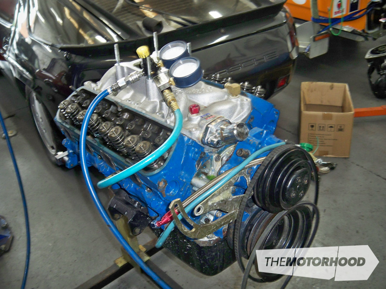
The engine was put on a stand and some basic checks were performed. With the rocker gear removed, the engine was given a cylinder leakage test to check ring-seal condition. Thankfully, it passed with flying colours.
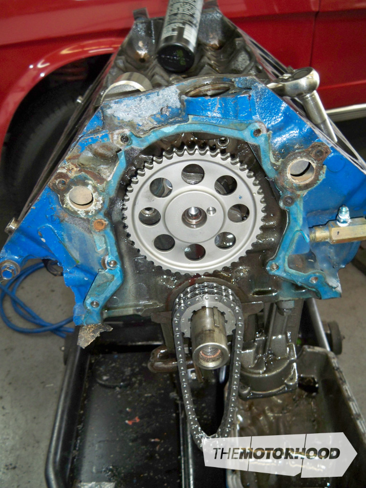
The heads, front of the engine, sump, and camshaft were all removed from the engine block. The block was then carefully drilled to accept the hydraulic lifter plate, with great care taken to remove any metal filings. The new Comp Cams Xtreme Energy XR276RF cam could then be installed and the cam timing checked and adjusted to the manufacturer’s specifications.
With the cam in, the team could focus on the heads, which were cleaned and checked before being dummy assembled on the engine. With the new set of Comp Cams roller rockers fitted to the heads, the pushrod length was determined (see below) and then the piston to valve clearance was checked. It was found that the exhaust valve had plenty of clearance, but the intake valve was in trouble, hitting the piston at the valve relief eyebrow. This meant that the valve pocket had to be opened up to get the desired piston to valve clearance (see below).
With the pistons returned with their newly modified tops, the piston to valve clearance was double checked on all cylinders, just to be sure that there was now sufficient clearance. Once it was determined that the clearancing had worked, the heads were installed for the final time, using the correct 7/16-inch to ½-inch washers and new ARP head bolts.
The rest of the engine could now be reassembled and fitted with the modified torque converter from Auto Trans. While the converter could have been left alone, it made sense to get it modified at the same time. The new cam’s rev range is 2200rpm plus, so the converter has been set to lock at around that same rpm level.
After being plumbed up, the engine was started and taken through a minor break-in process. Although it is a roller cam set-up, it is still worth it to be careful with the first half-hour running and to change out the oil and filter almost straightaway.
With the run-in procedure done, the oil was drained and filter cut open to check for any metal filing or signs of undue wear. All was well, and the car could be refilled with oil and once again strapped to the dyno for tuning.
Conclusion
With the timing needing adjustments to suit the new camshaft, and the carburettor needing both air and fuel adjustments, a final power run could be conducted. The results were a major increase in power throughout the entire rev range, with an increase of 60hp at 4500rpm through to a peak of 279hp at 5800rpm. That’s a 40 per cent increase in power from a simple head and cam swap, and one seriously happy Mustang owner!
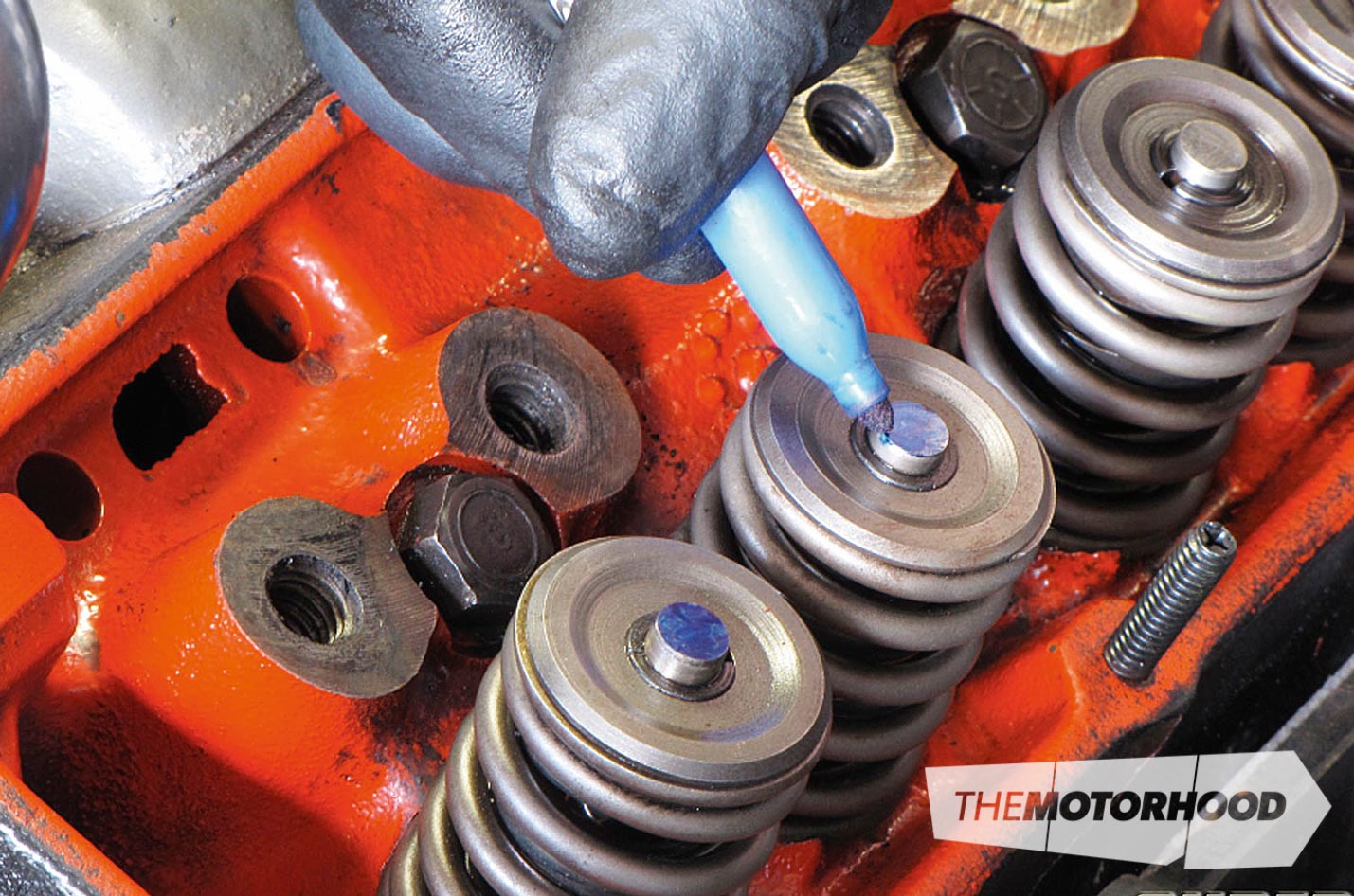
Calculating pushrod length
All you really need to check for proper pushrod length is a black felt-tip marker and a few tools. Simply take off a valve cover and rotate the engine until the rocker arm of your choice is on the base circle of the lobe. Loosen and remove the rocker arm. Clean the top of the valve-stem tip and then paint the tip with the black marker. Place the rocker back over the stud and adjust to correct valve lash. Then rotate the engine two complete revolutions. The rocker will then have left a witness mark on top of the valve tip.
If the pushrod length is correct, the witness mark should be located on the inboard third of the valve-stem tip. If the witness mark is too close to the intake side of the valve-stem tip, the pushrod is too short. If the witness mark is in the middle or towards the exhaust side of the valve-stem tip, then the pushrod is too long.

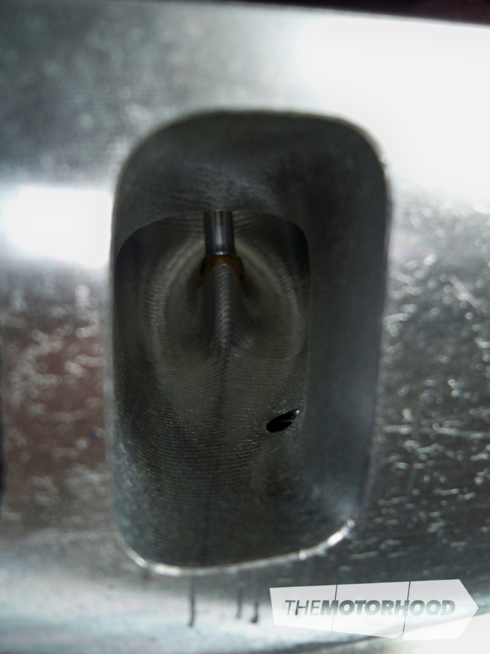
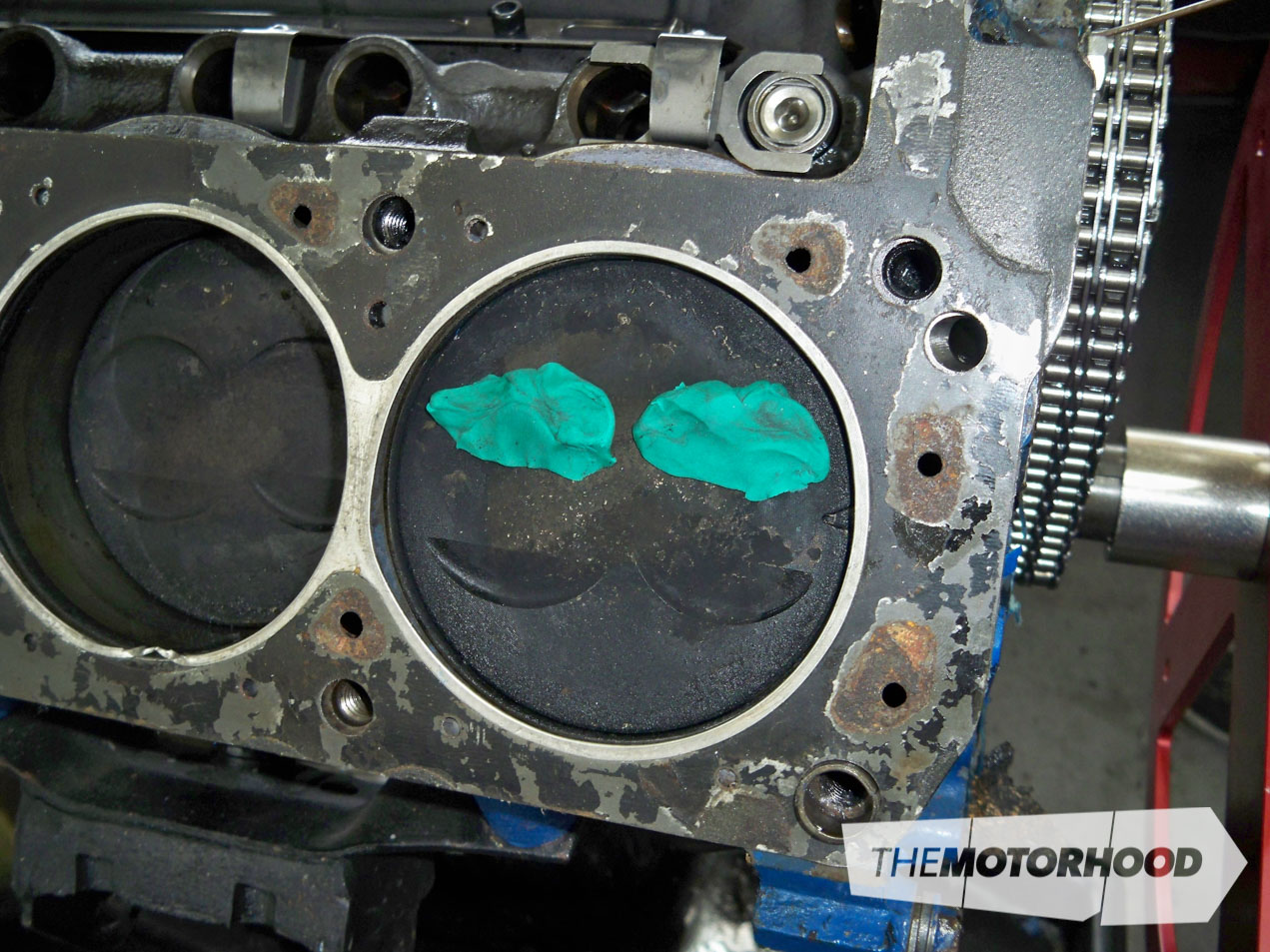
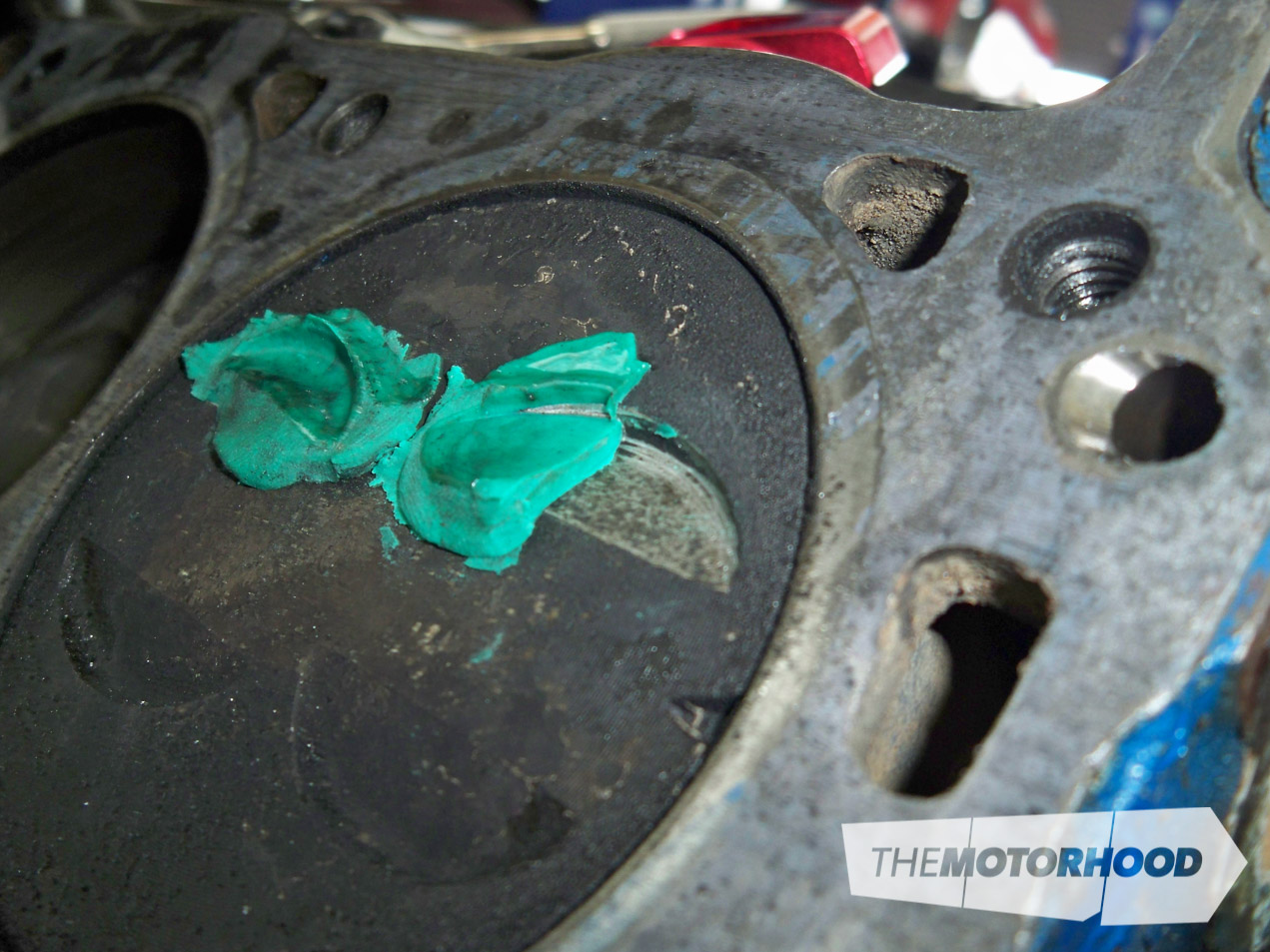
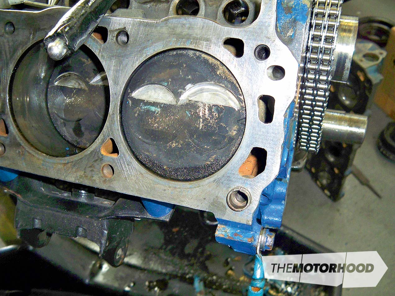
Clearances
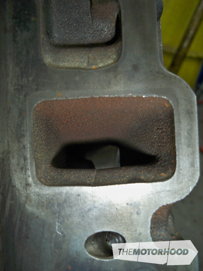
Prior to fitting the new heads properly, valve clearances were checked by simply putting plasticine on the pistons and running the valves through their motion
If this hadn’t been done to show there was a clearance issue, the valves would have bent as soon as the engine was fired up. Note how the valve indent is fractionally too big for the existing piston’s recess.
This article was originally published in NZV8 Issue No. 108. You can pick up a print copy or a digital copy of the magazine below: