
It’s a simple subject that becomes increasingly complex the further you look into it. We delve into the world of suspension and how you can use it to your advantage
When considering the suspension system of a car, it helps to imagine a car sitting on no springs, which will pretty much have the chassis lying on the ground. Now imagine the same car on a hoist, when the wheels will be hanging well below the chassis. The purpose of the suspension system is to suspend the vehicle in equilibrium, in such a way that any of the vehicle’s wheels will have sufficient upward or downward travel — without ever reaching the two extremes mentioned — to retain contact with a variable road surface.
Coil springs
Coil springs are commonly compared in terms of ‘spring rate’ — a measurement of the weight required to compress a spring by one inch. A spring with a rate of 200 pounds/inch will compress by one inch for every 200 pounds’ load placed on it. A spring with an 18kg/cm rate will compress by 1cm for every 18kg of load.
You may also note that many coil springs can be had with either a linear or progressive rate. What does this mean? ‘Linear-rate’ springs compress at the same spring rate, regardless of compression or load on the spring. In comparison, the spring rate of progressive-rate springs increases the more they are loaded or compressed. The purpose of a progressive spring rate is essentially to eke the best of both worlds from the spring — a softer spring rate for minor irregularities in the road surface, with a progressively increasing spring rate to limit body roll as the car is driven harder.
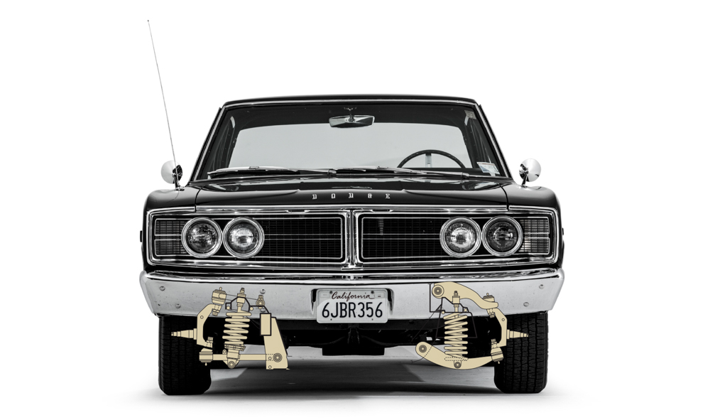
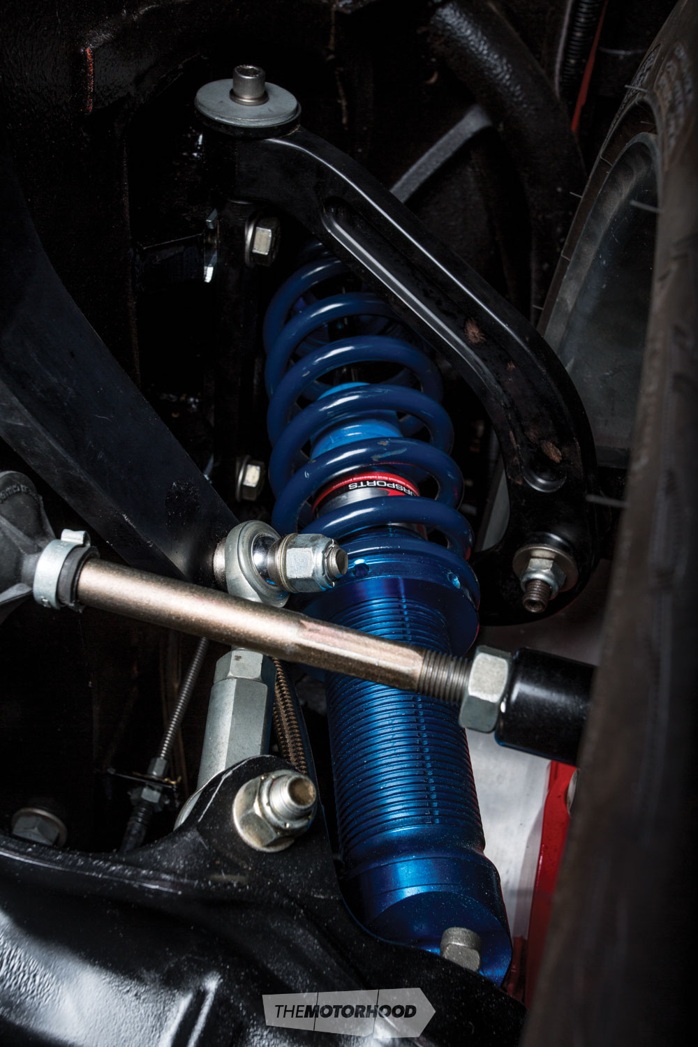
Assume the B-body Mopar didn’t run torsion bar front suspension — coilover (L) and coil spring (R).
Springs
The springs are one of the major parts of any vehicle’s suspension system. A mental image of a coil spring is probably the first thing that comes into most people’s minds when talking about vehicle suspension. Automotive springs are most commonly identified as coils, leaves, or torsion bars, although airbags and hydraulic rams can also technically be counted as spring equivalents.
The spring is required to support the vehicle’s mass, as well as to allow the wheels and tyres a degree of upward/downward movement to best contact a variable road surface.
Leaf springs
Leaf springs operate on a rudimentary design, generally based on multiple ‘leaves’ — primarily, semi-elliptical sheets of steel — stacked on top of each other, getting progressively shorter in length. The ‘top’ leaf is the longest, meaning it will have the most flex in it. As the load increases and the top leaf straightens out, it meets resistance from the shorter leaf below it — this continues, with each leaf adding an extra, and increased, degree of resistance.
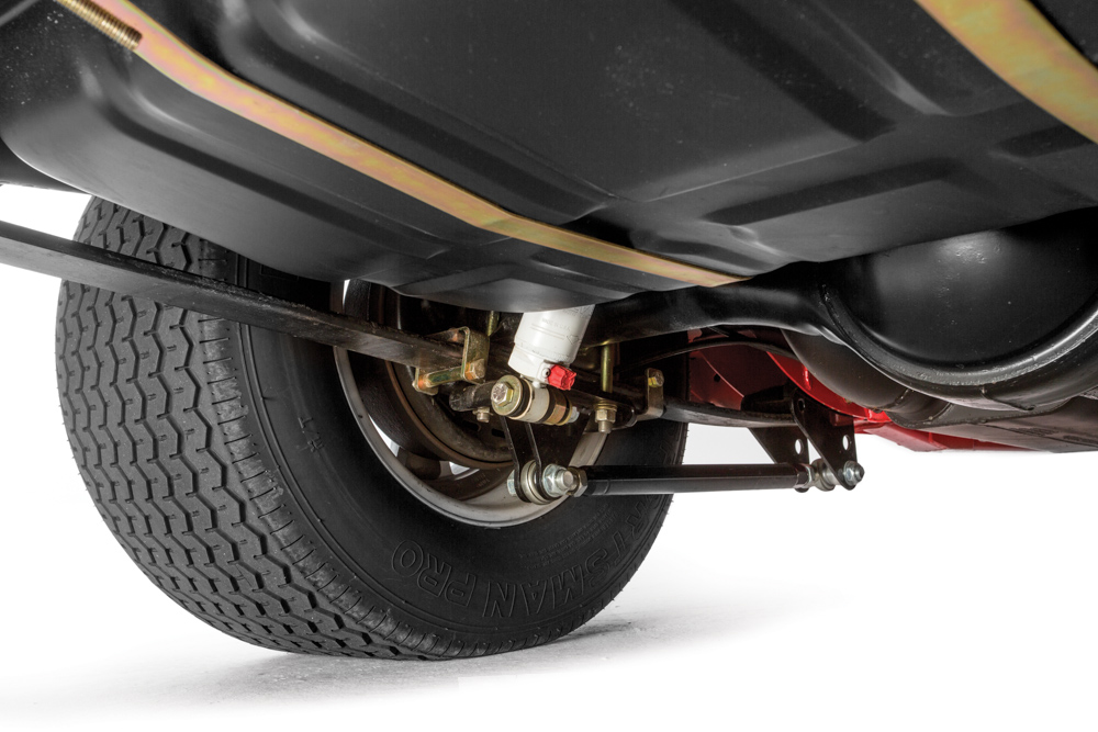
Traction bars are commonly used in leaf-sprung vehicles with powerful engines. Under hard acceleration, such as on a drag strip, the axle may try to twist, causing the leaf spring to ‘wrap up’, or bend. The common CalTracs-style system uses a bell-crank assembly, operated by a pivoting rod mounted to the base of the leaf spring, which transfers the axle’s twisting motion into downward force onto the top spring’s weak point, counteracting wrap up, and improving traction.
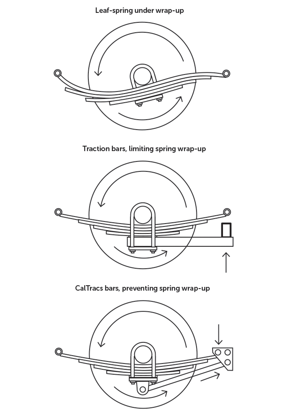
Traction bars also take the form of what are known as ‘slapper bars’ — a far simpler design. These are installed between the leaf spring and the spring plate and are designed to apply pressure to the leaf spring’s front ‘eye’ under hard acceleration, physically limiting spring wrap up.
Torsion bars
Torsion-bar suspension was an extremely popular system across the world, although most people will associate them primarily with Chrysler vehicles manufactured around 1957. The torsion bar acts as the spring in such a system. It is a metal rod or bar, firmly affixed to a chassis mounting point, with the other end fixed to a pivoting ‘lever’, primarily the lower control arm. As the control arm moves up and down over road undulations, it twists the torsion bar, the resistance of which acts in the same way that a spring regulates bumps.
One of the biggest advantages of torsion-bar suspension is its ease of use as far as adjustment and maintenance are concerned. Ride height, and the associated suspension properties, can be altered simply by turning each side’s torsion-bar adjuster bolt. In Chrysler suspension systems, turning the bolt clockwise will increase ride height, while counterclockwise rotation will lower ride height.

The ‘spring rate’ can also be changed simply by swapping to a torsion bar with a different rate, rather than removing and replacing coil springs.
Shock absorbers
The shock absorber’s main function is to control the vehicle’s springs and maintain tyre contact with the road when the vehicle hits a bump and the spring is compressed. This compression creates kinetic energy, and the kinetic energy is released when the spring extends. If there were no shock absorbers, there would be nothing to control this release of kinetic energy, and the vehicle would bounce down the street uncontrollably. It is perfectly explained by Newton’s third law of physics: for every action, there is an equal and opposite reaction.
A shock absorber controls this release of energy by exploiting some simple hydraulic principles.
All hydraulic shock absorbers operate on the principle of converting kinetic energy into thermal (heat) energy and then dissipating that heat into the atmosphere. They do this by forcing the oil inside the shock absorber to flow through restrictive orifices and multistage valves to generate hydraulic resistance. Shocks with adjustable valving offer users the ability to fine-tune each shock absorber’s damping to suit particular preferences.
The shock-absorber effect also affects weight transfer, and it is possible to select — or adjust — shock-absorber valving to behave in a particular way. For example, the weight-transfer properties used in drag racing will be substantially different from those of a car used on a circuit. If precise fine-tuning is important, adjustable shocks offer greater flexibility with compression and rebound. Single-adjustable shocks generally offer adjustment of compression or rebound only, while some, such as those manufactured by QA1, offer simultaneous compression and rebound adjustment with each increment. Double-adjustable shocks offer independent adjustment of both compression and rebound, while high-end triple-adjustable shocks generally offer two compression adjustments and one rebound adjustment. In most street-driven vehicles, correctly valved nonadjustable shocks or single-adjustable shocks will be sufficient.
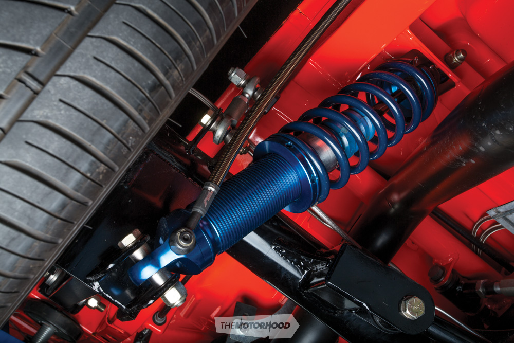
Coilovers
‘Adjustable coilover suspension’ is, as the name suggests, a coil spring operating over a shock absorber, all contained in one unit. Adjustable coilovers include a threaded shock body, allowing a threaded spring perch and locking collar that can be adjusted (wound up or down) with special C-spanners to raise or lower ride height. Many coilover shocks available on the market are also ‘damper adjustable’, meaning that they include an adjuster knob allowing adjustment in shock valving — an important tool in fine-tuning a vehicle’s handling characteristics.
Coilovers are a popular option with aftermarket-style four-link rear ends and double-wishbone independent-front-suspension (IFS) set-ups, and can usually be purchased as bolt-in replacement units for vehicles originally equipped with MacPherson-strut suspension systems.
The aftermarket has many kits allowing coilovers to be installed in a range of chassis. However, in the majority of older vehicles, these kits will also require reinforced mounting brackets and associated componentry, such as tubular control arms. This is due to the inherent extra load that coilover mounting points are subject to — from the built-in coil-spring compression and rebound forces — in comparison with non-coilover shocks.
Most aftermarket control arms will be of a tubular construction, but this is not necessarily for strength considerations. While properly manufactured tubular control arms are sufficiently strong, they are substantially cheaper to produce in aftermarket quantities, because of the machinery investment required for OEM-style stamped control arms.
Sway bars
The ‘sway bar’ (or ‘anti-roll bar’) is a device designed to counteract body roll by anchoring the vehicle’s left and right suspension to fixed points on the chassis. At the front end, the sway bar attaches to the lower control arms and is mounted on the chassis, while the rear end is fixed to the diff housing and is mounted to the chassis. The resistance to body roll is affected by the torsional stiffness of the sway bar, which is usually determined by diameter or whether it is of a solid or hollow construction.
When cornering, as the body begins to roll, differences between the suspension load of the inner and outer wheel cause the sway bar to twist — its resistance to twisting is what determines how much or little the body roll is reduced. A sway bar of a larger diameter, or solid construction, will generally have a greater torsional stiffness than a smaller-diameter sway bar, or one of hollow construction.
A sway bar’s swing-arm length is also a factor in determining its anti-roll effectiveness. When viewing the suspension assembly top-down, the sway bar’s fixed chassis mount will be offset from the mounting point on the lower control arm or the diff housing. The ‘swing-arm length’ is simply the distance between the chassis and suspension mounting points. A longer swing-arm length reduces stiffness, reducing body roll less, while a shorter swing-arm length increases stiffness, reducing body roll more.
Bushes
Suspension bushes act as a sort of cushion between moving suspension parts to prevent metal-on-metal contact. This helps to dampen any shocks transmitted through the suspension system, while retaining the vehicle’s suspension geometry. The most common form of suspension bushing is for a pivoting suspension component, such as control arms or four-link bars. Construction is generally of a flexible material — primarily rubber or polyurethane — moulded into a tubular form, with an internal ‘crush tube’ to house the fixed pivot point, which is usually a through-bolt.
Most road vehicles use rubber bushes, which are cheap to purchase and are of a reasonably soft construction. This allows for reduced transmission of both noise and vibration. However, rubber bushings are not suited for high-load applications, in which the bush is susceptible to deforming, and rubber is also adversely affected by extraneous substances such as oils and foreign matter.
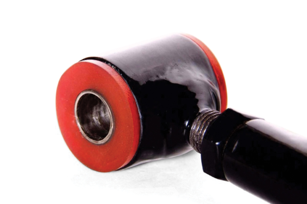
Polyurethane bushes are more solid and durable than rubber bushes. The material’s inherent rigidity and resistance to impact and abrasion make bushes made from it more suitable for applications in which the suspension components are under increased pressure — essentially, anything more than a leisurely drive down to get some groceries. If you’re fond of hoofing around the back streets or taking your car to the track, it’s likely that factory rubber bushes are ‘deflecting’ — deforming when under load, due to their flexible construction — which, in turn, affects critical areas of the suspension geometry.
Solid suspension bushes — in the form of heim joints, or rose joints — are, technically, the most effective means of avoiding bushing deflection. Their solid construction transmits far more shock and noise than does flexible construction and requires periodic lubrication, but the virtual lack of deflection can make them a feasible bushing option in race-only vehicles.
Lateral location
Panhard bar: A ‘Panhard bar’ is a rear suspension link, primarily used on coil-sprung live rear axles. The bar has a pivot point attached to the axle housing on one side and attaches to another chassis-mounted pivot point on the opposite side. The Panhard bar means the axle can only travel in a vertical arc, restricting lateral suspension movement and maintaining rear suspension geometry. It does not affect longitudinal movement, meaning that the suspension system will also require trailing arms (four-link arms) or ladder bars.
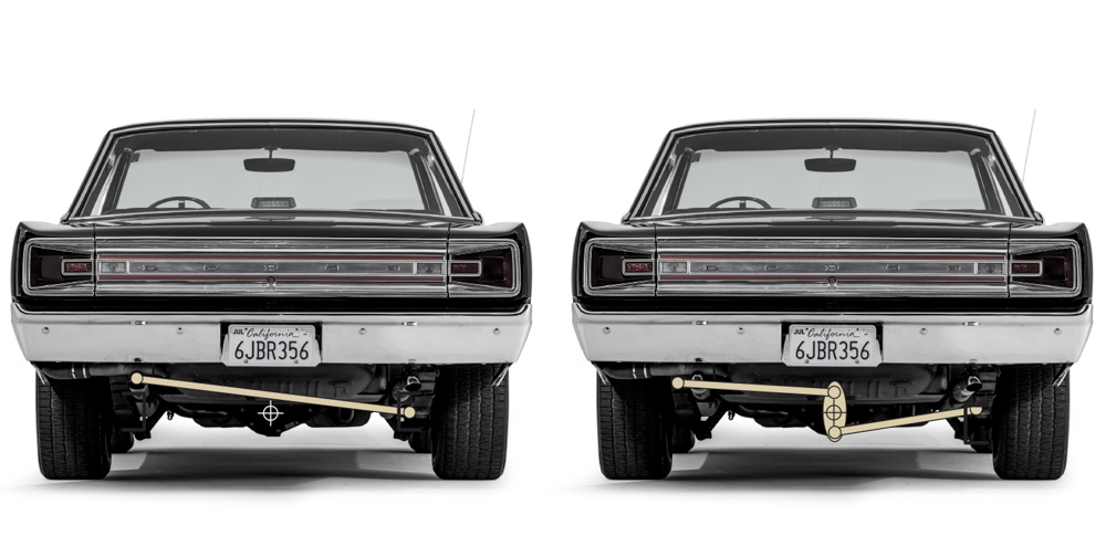
Watt’s linkage: A ‘Watt’s linkage’ is a system intended to limit lateral suspension movement on a live rear axle. It achieves this by keeping a central pivot point moving in an approximately straight, vertical line as the suspension travels up and down. A Watt’s linkage comprises three pivoting rods; one short rod in the middle, with each end connected to a longer rod — both of the same length — with the other end connected to a chassis-mounted pivot point. The vertical movement provided by a Watt’s linkage is not a precise straight line, though it is a near enough approximation.
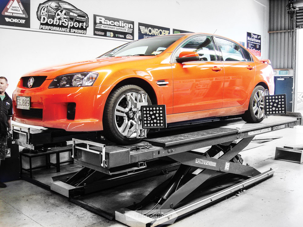
Alignment (Words: Gareth Court)
Toe angle
The ‘toe angle’ refers to the measurement between the front wheels relative to each other, when viewed from directly above. ‘Toe in’ (or ‘positive toe’) is when the wheels are pointed slightly inwards, with the front of the wheels closer together than the rear. ‘Toe out’ (‘negative toe’) is the pposite, with the front of the wheels farther apart than the rear.
Toe angle can have a big impact on tyre wear and plays a large part in determining a vehicle’s handling characteristics. Toe out can cause a vehicle to become twitchy and unstable in a straight line, as the toe angle causes the inner wheel to turn at a tighter radius than the outer wheel.
Because of how varied the effects of toe angle are on the handling characteristics of different vehicles, there is no cut-and-dried rule about what is optimal — the best way would be to fine-tune your vehicle’s handling characteristics through trial and error.
Caster angle
‘Caster’ is the angle between the steering axis and vertical, when viewed side on. The ‘steering axis’ is an imaginary line intersecting the upper and lower ball joints on vehicles with double-wishbone front suspension, or between the upper strut bearing and the lower ball joint on MacPherson strut–equipped vehicles.
Caster is intended to provide directional stability, and most vehicles tend towards positive caster, which provides good steering feedback and self-centring steering force. Negative caster would give vague steering feel and little to no self-centring steering force.
Camber angle
‘Camber’ refers to the inboard or outboard tilt of the top of the tyres when viewed directly from the front or rear of the vehicle. ‘Negative camber’ is when the top of the tyre is tilted inboard (towards the centre line of the vehicle), while ‘positive camber’ is when the top of the tyre is tilted outboard (away from the centre line of the vehicle).
The function of tyre camber is to maintain an even tyre contact patch — utilizing the maximum tyre tread width — during cornering. A small degree of negative camber is generally beneficial, in that it can help neutralize the loaded outside wheel’s natural tendency towards positive camber when cornering. However, excessive negative camber can have the negative effect of rapid tyre wear, a reduced tyre contact patch, and stress on steering and suspension components.
Ackerman angle
The ‘Ackerman angle’ refers to toe out while a vehicle is turning. As a vehicle turns, the inside wheel needs a little bit more turn angle than the outside wheel — just a small amount, though. At 20 degrees of steering lock, the Ackerman angle may be only two degrees — this means that, while the outer wheel is turned at a 20-degree angle from straight, the inner wheel is turned at a 22-degree angle.
If a car had zero Ackerman, both wheels would be at 20 degrees of lock. This is an undesirable characteristic, as zero Ackerman can induce understeer, provide unresponsive steering feedback, and increase tyre wear.